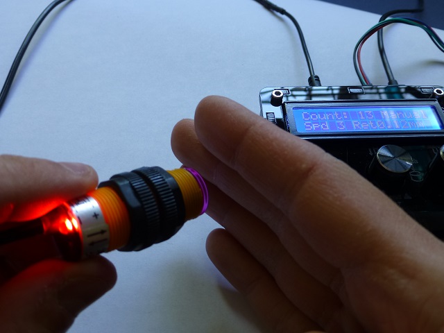
The dispenser has an optically isolated input for triggering the dispenser remotely. It also provides power from the USB port, this makes it very flexible since it allows you connect simple switches, other systems with a wide signal input range (3-12V) and even sensors powered directly from the dispenser.
Note 1: Always check with a multimeter to see which strands in the cable correspond to which pins in the plug, a mix up can short the USB port and damage your power supply and/or device.
Note 2: Shut down the unit when plugging the cable to prevent accidental dispensing.
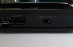
Troubleshoot: If the unit doesn’t respond with the foot switch or another external signal, make sure that the plug is inserted all the way in.
The first example is by using an external switch. You’ll need a regular 3.5mm cable with 3 conductors like this one:

To start dispensing you need to short the first two pins, 1 and 2 in this diagram: (Block on the right represents the dispenser)
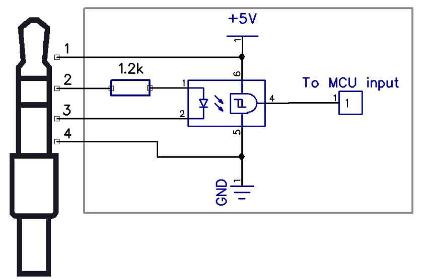

As you can see, the internal LED from the optocoupler is powered by the same USB 5V line as the dispenser but only when the switch is closed, its ground is connected by the 3rd conductor in the plug.
Now to connect with a 3D printer or similar device:
Here you can isolate the input completely, you’ll need a 3.5mm jack with 4 conductors:


Please note the internal resistor is rated for 1/4W power dissipation and the LED voltage drop is around 1.2V
If you don’t have a 4 conductor cable you can also use a regular one, with the same connection shown above minus the 4th cable. The only difference is that the dispenser and printer grounds will be shared. There shouldn’t be problems with this but in some cases it could cause instability in the printer due to the extra noise of the dispenser.
If you want to extend the trigger voltage to 24V an external 1k resistor has to be added in series like this:

This is because the 3.5mm female connector is only rated for 12V also the power dissipated by the internal 1.2k SMD resistor would be too high.
And lastly, pin 1 provides a 5V output which you can use to power an external sensor, in this case a proximity IR. Which is connected like this:
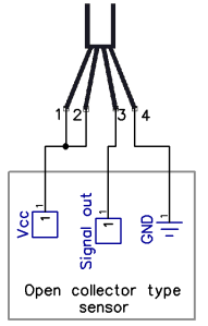
In this case the sensor has an open collector output, what this means is that it can’t source any current to power the LED, instead it’s only able to sink it. This is why you need to tie the 5V from pin 1 to pin2. The output then just closes or opens the LED’s path to ground thus turning it on and off.